Wattmeter
Principle of operation
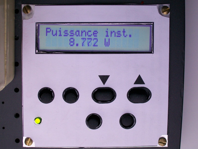
The wattmeter computes the power used by a device by measuring simultaneously the voltage and current going through the device. As it is powered by the alternative voltage of mains, the wattmeter measures the instantaneous power several times per cycle and computes its average.
The wattmeter has a low voltage part (microcontroller) safe to tinker with and another part directly connected to mains power which might be quite dangerous when you put your finger in the wrong place. In order to be able to work on the low voltage part safely, one has to make sure that it is completely isolated (galvanic insulation) from mains voltage. The achieve this insulation the voltage and current are measured through transformers (voltage and current transformers)
The low voltage part is powered with 5 V coming from a switch mode power supply salvaged from an AC adapter. It must be also noted that the positive and negative supplies for the op amp are produced from the 5 V by a MAX232 circuit. This IC can deliver a maximum of 10 mA, which is more than enough as no op amp has to deliver a lot of current.
The voltage and current are measured by the analog/digital converter of a PIC18F2610 microcontroller which computes the instantaneous power and its average over one second (50 cycles of mains voltage). It also computes other values like the RMS values of voltage and current, the apparent power, or the power factor.
Voltage measurement
The voltage across the device under test is measured through a voltage transformer, basically it is a normal transformer whose secondary winding is left open. Here it is the transformer of an old mobile phone charger.

At the output of the transformer, there is an alternative sinusoidal voltage the amplitude of which is around 10 V (The voltage oscillate between -10 V and +10 V). The microcontroller can only measure voltages between 0 and 5 V, thus the following circuit is used to divide the voltage by a factor of 10 and add an offset of 2.5 V to bring it in the measurement range of the PIC.
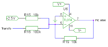
The mains voltage is not expected to vary a lot for different devices which could be tested, hence it is safe to use one single gain. It should be noted that the gain we chose is not optimal because the output voltage oscillate between 1.5 V and 3.5 V which does not cover the whole measurement range of the PIC. In order to correct this, the R16 resistor should be slightly lowered.
Current measurement
The current is measured through a current transformer. This current transformer is built by passing one of the mains wire through a ferrite toroid that has N turns of copper wire (N is large). The primary winding of the transformer is made of only one turn and the secondary winding has N turns. When the secondary is short-circuited, the current going through it equals the primary current divided by N. In this case I took in my coil box a toroid coil which looked like it had a lot of turns. The secondary is connected to a low value resistor the voltage across which is proportional to the current going through it.

The current going through the device under test can vary over a wide range of values from a few milliamps to several amperes. In order to get the best precision for all the possible values, we use three different amplification factors before the PIC adc. The measured voltage representing the measured current is multiplied by 1, 10 and 100 and shifted by 2.5 V to have the zero centered in the middle of the PIC adc range.
Below is the part of the circuit which amplifies the current signal by a factor of 10. The amplification and offset are done simultaneously by op amp U3. The rest of the circuit is used to limit the output voltage between 0 and 5 V before it is measured by the microcontroller. The op amp U6 is a voltage follower which gives this part of the circuit a low output impedance, which allows a shorter acquisition time during the analog/digital conversion (the charge of the hold capacitor is faster). I am not sure that this is really necessary...

Speaking about unnecessary things, there is also an instrumentation amplifier of unity gain at the output of the current transformer, it is probably not necessary either.
One problem detected by a commenter on hackaday is that the voltage output of the current transformer is not completely in phase with the current (why ?), and in some situations, this phase difference may introduce a large error in the power measured. By connecting a purely resistive load (a resistor) I could measure this phase difference to around 10°. It is corrected in software by delaying the voltage sampling relative to the current sampling.
The correction induced is far from negligible because without it, the power indicated for some switch mode power supplies was negative.
Analog digital conversion
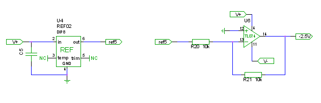
In order to get the best precision and reproducibility of the analog to digital conversion, this circuit has a 5 V voltage reference which is divided by 2 to produce the -2.5 V used to shift input voltages.
The power used by a device is estimated by measuring the instantaneous power a large number of times by cycle of mains voltage. This means that the microcontroller has to perform a lot of measurements during the 20 ms duration of one cycle. The PIC18F2610 has a theoretical acquisition speed of 100000 samp./s, which would give 1000 samp./cycle (both voltage and current have to be measured). This acquisition speed leaves little time for other operations : the PIC has a max speed of 10 MIPS which leaves only 100 instructions per sample at the maximum speed. It is likely possible to achieve but requires to fine tune the code.
One can also use the periodicity of the mains voltage and perform the acquisition over several cycles, for example in over one second which means 50 cycles. If the number n of samples has to common divider with 50, one can be sure that during these 50 cycles no two samples will be acquired at the same time of the cycle and one has n effective samples per cycle. Below is shown an example where we took 51 samples over 5 cycles. The position of the samples occurring after the first cycle was shown in the first cycle where there are effectively 51 samples/cycle

Calibration
This system needs to be calibrated in order to produce a accurate measurement. One needs to use it with a device of known power to calibrate the conversion factors of voltage and current. The RMS voltage and current measurement also need a calibration with a known mains voltage. For now, these two calibration constants are hard coded in the firmware, a calibration menu has to be added.
LCD display


The LCD display used in this project was salvaged from a printer (probably a Lexmark T522). The module consists of a display which has two lines of 16 characters and 6 buttons (marking : BJ5200G02004). This module is controlled by i2c and was not really difficult to make working thanks to other people who already did the hard work :
and the links contained in these two pages.
Todo
Quite a few things are left to be done :- Developing a calibration menu in the firmware ;
- Display the energy used in kWh, give the corresponding price ;
- Test this wattmeter against an (good) commercial unit ;
- Find out why the power display for a sleeping switch mode power supply is negative.
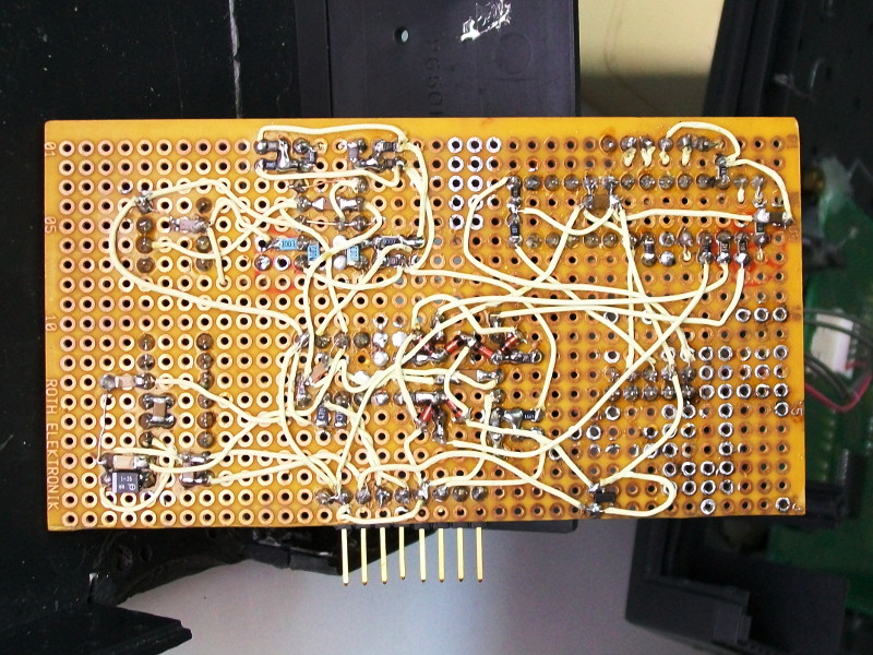
Pictures