Sunrise Alarm clock

Principle of operation
This is an alarm clock simulating the sunrise, which means that a few minutes before the alarm goes off, it shines some light whose brightness increases over time.
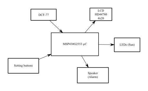
The alarm clock is built around a MSP430G2553 microcontroller compatible with the MSP430 Launchpad from Texas Instrument.
It features a DCF77 module which sets the clock automatically through radio waves.
The display is a character LCD module with 4 lines of 40 characters driven by a HD44780 controller.
The light is produced by several white LEDs which shine their light through the translucent front face of the clock.
The audible alarm consists of a selected melody played by two speakers.
Download the (in)complete schematics of the alarm clock : (pdf)(png)
The MSP430G2553 microcontroller

The MSP430G2553 from TI is a 16 bits, very low power microcontroller. It was choosen for several reasons :
- It is compatible with the MSP430 Launchpad from TI, which can be used as a very cheap ($4.30) USB programmer for this family of chips.
- It is the most powerful of the MSP430G family, its 16 kb of flash memory and the bigger number of input/output pins are not too much for this project.
- It is cheap ! TI even provides free samples...
The display

The display is a dot matrix character LCD module with 4 lines of 20 characters driven by a HD44780 controller. For better readability the digits of the time are displayed on 3 lines through the use of a few custom characters. The menus and other information are displayed in text form
Driving the display
Even if the MSP430G2553 has got more input/output pins than most of similar ICs, this project still needs one or two more pins. In 4-bits mode, a HD44780 display needs 6 control lines: D4,D5,D6,D7, RS (Data/Command) et E (Clock). In order to reduce the number of pins needed on the µC I have included a serial-in parallel-out shift register MC14094(pdf) which can drive 8 digital outputs from 2 inputs (at least Data and Clock)
The HD44780 data lines are driven through the shift register whereas the clock signal (E) is directly connected to the µC. With this setup, the µC can set the data lines before sending a clock pulse.
Contrast tuning
This kind of LCD has a V0 (or VE) pin used to adjust the contrast of the display, it is usually sufficient to connect a variable resistor between this pin and the ground to adjust the contrast. Nevertheless the contrast of the display I used remained very poor even when V0 was directly grounded. Meaning that I should provide V0 with a negative voltage to increase the contrast.
This negative voltage is generated by a charge pump circuit described bellow.

The input of the circuit is connected to a pin of the µC which outputs a square signal oscillating between 0V and 3V.
- When the input is +3V, the left plate of the capacitor C1 accumulates a positive charge and pushes the positive charges of the other plate through the diode D1 (bleu path).
- When the input goes to 0V, the charge accumulated on the left plate of the capacitor C1 are taken away, and the right plate gets its positive charges back through D2 (these charges come from the top plate of the capacitor C2). (red path)
The result of this cycle is that the top plate of C2 gets a negative charge thus there is a negative voltage (-U) between this plate and ground. This explains why this circuit is called charge pump : the oscillation of the voltage across C1 pumps the charges in C2 through the diodes.
This explanation is made with positive charges (the conventional charge in electronics). One should not forget that the actual charges are negative electrons, the explanation above is still true ! (after changing a few signs)
Back-light
The back-light is driven by pulse width modulation (PWM) by the microcontroller. This allows to adjust its intensity and to fade the light when it switches on or off
Automatic time setup (DCF-77)
 I scavenged a DCF77 from an old alarm clock (indeed, I took apart an alarm clock to build an alarm clock !) and I integrated it in this project. The DCF77 signal is transmitted at a frequency of 77.5 kHz from Germany. It is amplitude modulated to carry the legal time based on an atomic clock.
The information is transmitted in binary, at the rate of one bit per second. At the beginning of each second, the amplitude of the signal is reduced to 25% of its maximum level, it goes back to 100% after 100 ms to transmit a '0' or after 200 ms to transmit a '1'. The 59th second is not modulated to . The time itself is coded from the 20th second. Wikipedia gives all the details on the protocol.
The module handles all the analog part of the signal processing and has got a single digital output whose level (0 or 1) indicates the level of the signal (25% or 100%). The microcontroller is responsible for decoding the information and extract the current time. It is very important to check the integrity of the received signal with its multiple parity bits (and prevent the time from being setup incorrectly).
Lighting — sunrise
The light which simulates the sunrise is produced by a handful of white LEDs pointing at the translucent front panel of the clock. The variations the light intensity is produced by PWM with the microcontroller driving the base of a switching transistor.

Sound
The audible alarm consists of a selectable melody played through two speakers located on the sides of the clock. In order to simplify coding and save processing time, the tunes are produced by a square wave with proper frequency. The volume can be roughly adjusted varying the pulse width of the square wave (I know it shouldn't be done like this, but it still works). I have added a capacitor across the speaker to smooth the signal a little bit.
One day, I should try to code sinusoidal tunes through an analog output of the µC (PWM+low-pass filter) to check if the µC can still follow...
Battery backup
In order to keep accurate time when the power connection is removed, I included a backup battery which allows the µC to carry on with time counting even when mains power is lost. Nevertheless it can only count time and every other peripheral has to be deactivated (the backup power source is a small CR2032 battery). Hence the µC must be informed when the clock is on backup power.

This is the role played by the system shown above. When main power (+3V) is active, the µC is powered through D1 and the pin P1.4 of the µC is high through D3. When main power is lost, the backup battery powers the µC through D2, the latter knows it is on backup because its P1.4 pin goes to low. Thus it can go to sleep mode and only wake up to count time.
Pictures


Video
In this video I set the sunrise delay (from no light to full power) to one minute to keep the video short, but it is usually set to something like 20 minutes.