Nixie tubes clock

This is a simple clock built from scavenged nixie tubes (the electronics recycle bin of the Max Planck Institute in Stuttgart is a gold mine)
Principle of operation
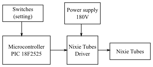
The clock is driven by a PIC 18F2525 microcontroller clocked by a 32768 Hz quartz oscillator. There are only two setting buttons, the first one sets the hours and the second one sets the minutes.
In order to reduce the quantity of components and the complexity of the circuit, the four nixie tubes are multiplexed. They are switched on one by one through the anode drivers and the corresponding digit is selected by the cathode driver. This cycle repeats fast enough so that the digits look continuously on.
Anode driver
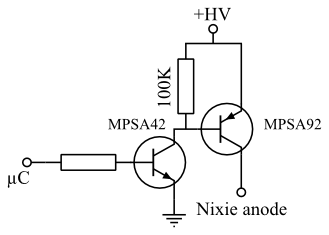
The anode of each one of the four nixie tubes is driven by the circuit shown above. It consists of two high voltage (300 V) transistors, one NPN (MPSA42) and one PNP (MPSA92).
Cathode driver
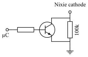
In order to drive the cathodes, the transistor does not need to be high voltage tolerant, the 100k resistor between the emiter and the collector of the transistor keeps the cathode voltage low enough to keep the transistor from breaking but high enough to prevent the digit for lighting up.
High voltage power supply (180 V)
The high voltage (around 180 V) power supply of the tubes is produced by a boost switch mode power supply built around a NE555 chip. This kind of power supply, widely used in the nixie tubes community, is very well explained on this page. The biggest modification I made was to change the T1 transistor for a LM393 comparator.
Pictures


